- 您现在的位置:买卖IC网 > Sheet目录344 > MSL2041GU (Atmel)IC LED DRIVER 4 STRING
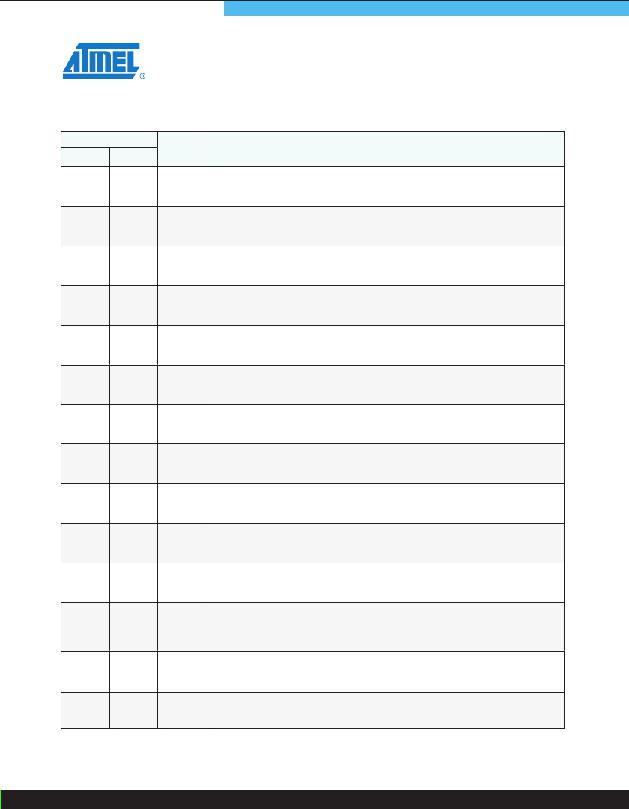
PIN
MSL2041 MSL2042
NAME
DESCRIPTION
6
19
20
21
22
23
25
26
27
28
29
30
31
32
-
19
20
21
22
23
25
26
27
28
29
30
31
32
3, 4, 5
G2
S2
S3
G3
D3
VDD
CVDD
VCC
VIN
GND
FBI2
FBO2
FBI1
CGND
Gate output 2
Gate drive output for external MOSFET 2. Connect G2 to the gate of the external MOSFET
driving LED string 2. If unused, connect G2 to ground.
Source sense input for string 2
Connect S2 to the source of the external MOSFET, and to the current sense resistor for
LED string 2. The full scale LED current is reached when 500mV is across the current sense
resistor. If unused, connect S2 to VDD.
Source sense input for string 3
Connect S3 to the source of the external MOSFET, and to the current sense resistor for
LED string 3. The full scale LED current is reached when 500mV is across the current sense
resistor. If unused, connect S3 to VDD.
Gate output 3
Gate drive output for external MOSFET 3. Connect G3 to the gate of the external MOSFET
driving LED string 3. If unused, connect G3 to ground.
Drain sense input 3
Drain Sense Input for External MOSFET 3. Connect D3 through a resistor to the drain of the
external MOSFET driving LED string 3. If unused, connect D3 to ground.
2.5V internal LDO regulator output
VDD powers internal logic. Bypass VDD to GND with a 2.2μF ceramic capacitor placed close
to VDD.
Connect to VDD
Connect CVDD to VDD.
5V internal LDO regulator output
VCC powers internal logic. Bypass VCC to GND with a 2.2μF ceramic capacitor placed close
to VCC.
Supply voltage input
Connect a 12V ±10% supply to VIN. Bypass VIN to GND with a 1.0μF ceramic capacitor.
Power ground
Connect GND to system ground.
Efficiency Optimizer feedback input 2
Connect FBI2 to FBO2 of the previous device when using the devices in a chain
configuration. If unused, connect FBI2 to ground.
Efficiency Optimizer feedback output 2
Connect FBO2 to the feedback node of the second external string power supply through a
diode, or to FBI2 of the next device when operating the devices in a chain configuration. If
unused, leave FBO2 unconnected.
Efficiency Optimizer feedback input 1
Connect FBI1 to FBO1 of the previous device when using the devices in a chain
configuration. If unused, connect FBI1 to ground.
Connect to ground
Connect all CGND pins to GND as close to the MSL2042 as possible.
Atmel LED Drivers-MSL2041/2042
发布紧急采购,3分钟左右您将得到回复。
相关PDF资料
MSL2100BR
IC LED DRIVER 8 STRING
MSL2160DQ
IC LED DRIVER 16 STRING
MSL2162DQ
IC LED DRIVER 16 STRING
MSL3082CS
IC LED DRIVER 8 STRING
MSL3085BT
IC LED DRIVER 8 STRING
MSL3162BT
IC LED DRIVER 16 STRING
MSL3164BT
IC LED DRIVER 16 STRING
MSL3167GU
IC LED DRIVER 16 STRING
相关代理商/技术参数
MSL2041GU-R
功能描述:LED照明驱动器 Low-Cost, Simple 4-String LED Drivers RoHS:否 制造商:STMicroelectronics 输入电压:11.5 V to 23 V 工作频率: 最大电源电流:1.7 mA 输出电流: 最大工作温度: 安装风格:SMD/SMT 封装 / 箱体:SO-16N
MSL2042
制造商:ATMEL 制造商全称:ATMEL Corporation 功能描述:Low-cost, Simple 4-string LED Drivers with External Current Sink MOSFETs, 5000:1 Dimming Range and Per String PWM Input
MSL2042GU
功能描述:LED照明驱动器 4Str RGB or White LED Driver lighting RoHS:否 制造商:STMicroelectronics 输入电压:11.5 V to 23 V 工作频率: 最大电源电流:1.7 mA 输出电流: 最大工作温度: 安装风格:SMD/SMT 封装 / 箱体:SO-16N
MSL2042GU-R
功能描述:LED照明驱动器 4Str RGB or White LED Driver lighting RoHS:否 制造商:STMicroelectronics 输入电压:11.5 V to 23 V 工作频率: 最大电源电流:1.7 mA 输出电流: 最大工作温度: 安装风格:SMD/SMT 封装 / 箱体:SO-16N
MSL-204AUYL-4
制造商:Unity Microelectronics Inc 功能描述:LED Uni-Color Amber 592nm 4-Pin SMD T/R
MSL-204B
制造商:UOT 制造商全称:Unity Opto Technology 功能描述:ALLEDs
MSL-204DR
制造商:UOT 制造商全称:Unity Opto Technology 功能描述:ALLEDs
MSL-204HW
制造商:UOT 制造商全称:Unity Opto Technology 功能描述:ALLEDs
